Electricity is an essential part of our daily life. Understanding the basics of electrical circuits is very important. One of the most important tools for understanding electrical circuits is an ammeter. In this tutorial, we will discuss what is an ammeter, its circuit diagram, symbol, types, and applications.
What is an Ammeter?
An ammeter is an electrical device used to measure the flow of electric current in a circuit. The unit of measuring current is ampere. As the device measures the current in ampere, it is named as an ammeter or ampere meter. It is usually connected in series with the circuit element (or load). So all the current that flows through the load also flows through the ammeter.
In an ideal condition, the internal resistance of an ammeter is zero. But practically, it has some amount of internal resistance. So an ammeter has a very low resistance. As a result, it does not significantly affect the circuit it is measuring.
Ammeters are typically designed to measure direct current (DC) or alternating current (AC). These days, the work of an ammeter is often done with another device. A versatile device called a multimeter can measure multiple things along with the current.
Symbol of an Ammeter
The symbol of an ammeter is a circle with the letter "A" in the center. The circle represents the coil of the ammeter, and the letter "A" represents the unit of measurement, amperes.
This symbol is commonly used to represent an ammeter on electrical diagrams and schematics. The symbol is important in electrical engineering as it helps to identify and locate ammeters in electrical circuits. Now, let's take a look at the circuit diagram of an ammeter...
Ammeter Circuit Diagram
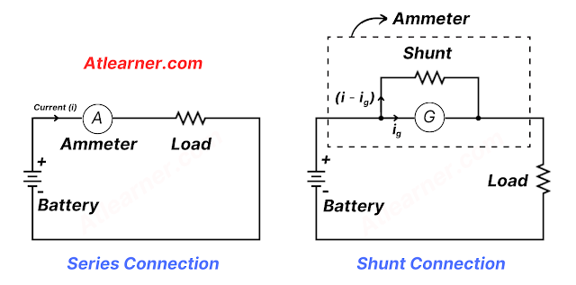
The construction of an ammeter can be done in two ways: series and parallel. Each method has its own advantages and disadvantages. They are used in different types of circuits depending on the requirements for the measurement.
Series Connection: First, let's take a look at the series connection of an ammeter -
Series connection involves placing the ammeter in series with the load whose current needs to be measured. This arrangement allows the ammeter to measure the same current that flows through the circuit element.
Series ammeters are typically constructed with low resistance. That is why it does not significantly affect the current flowing through the circuit element. This type of construction is useful for measuring low currents. It is often used in digital multimeters and other low-current measuring devices.
Shunt Connection: Now let's move on to the shunt connection of an ammeter. -
Shunt connection involves placing a shunt resistor in parallel with the ammeter to measure the current flowing through the circuit. Most of the current in the circuit flows through the shunt resistor, while a small fraction of the current flows through the ammeter.
Shunt ammeters are typically constructed with high resistance so that they do not significantly affect the current in the circuit. This type of construction is useful for measuring high currents. It is often used in power meters and other high-current measuring devices.
Note: The symbol G inside the circle is used for the galvanometer, Ig is the current that flows through the galvanometer, and Is = ( I-Ig) is the shunt current that flows through the shunt.
Types of Ammeters
There are several types of ammeters, which are classified based on their construction, range, and accuracy. Some common types of ammeters are Moving Coil Ammeter, Moving Iron Ammeters, and Digital Ammeter.
1. Moving Coil Ammeter:
Moving coil ammeters are the most common type of ammeter. They use a coil that is suspended on a pivot and is free to rotate. The coil is placed in a magnetic field, and when current flows through it, it rotates. The amount of rotation is proportional to the amount of current flowing through the coil.
Moving coil ammeters have a high degree of accuracy. They are commonly used in laboratories, workshops, and other applications
2. Moving Iron Ammeter:
Moving iron ammeters use a movable piece of iron that is attracted to a stationary piece of iron. The movable piece of iron is connected to a pointer, which indicates the amount of current flowing through the circuit.
Moving iron ammeters are more stronger than moving coil ammeters and can handle larger currents. They are commonly used in industrial applications and are particularly useful for measuring alternating currents.
3. Digital Ammeter:
Digital ammeters use digital technology to measure the amount of current flowing through a circuit. They are more accurate than analog ammeters and can display the current reading in a digital format.
Digital ammeters convert measured current into a digital signal that shows on a digital display. As a result, they are very accurate and easy to read. They are commonly used in automotive, marine, and other mobile applications.
Applications of Ammeters
Ammeters are used in a wide range of applications, including:
1. Automotive Applications: Ammeters are commonly used in automobiles to monitor the charging system and to detect any problems that may arise.
2. Industrial Applications: Ammeters are used in industrial applications to monitor the performance of machinery and to detect any problems that may arise.
3. Laboratory Applications: Ammeters are used in laboratories to measure the flow of current in experiments and also to monitor the performance of electrical devices.
4. Household Applications: Ammeters are used in household appliances such as refrigerators, air conditioners, and washing machines to monitor the flow of current and to ensure safe operating conditions.
Continue Reading...


Post a Comment (0)